
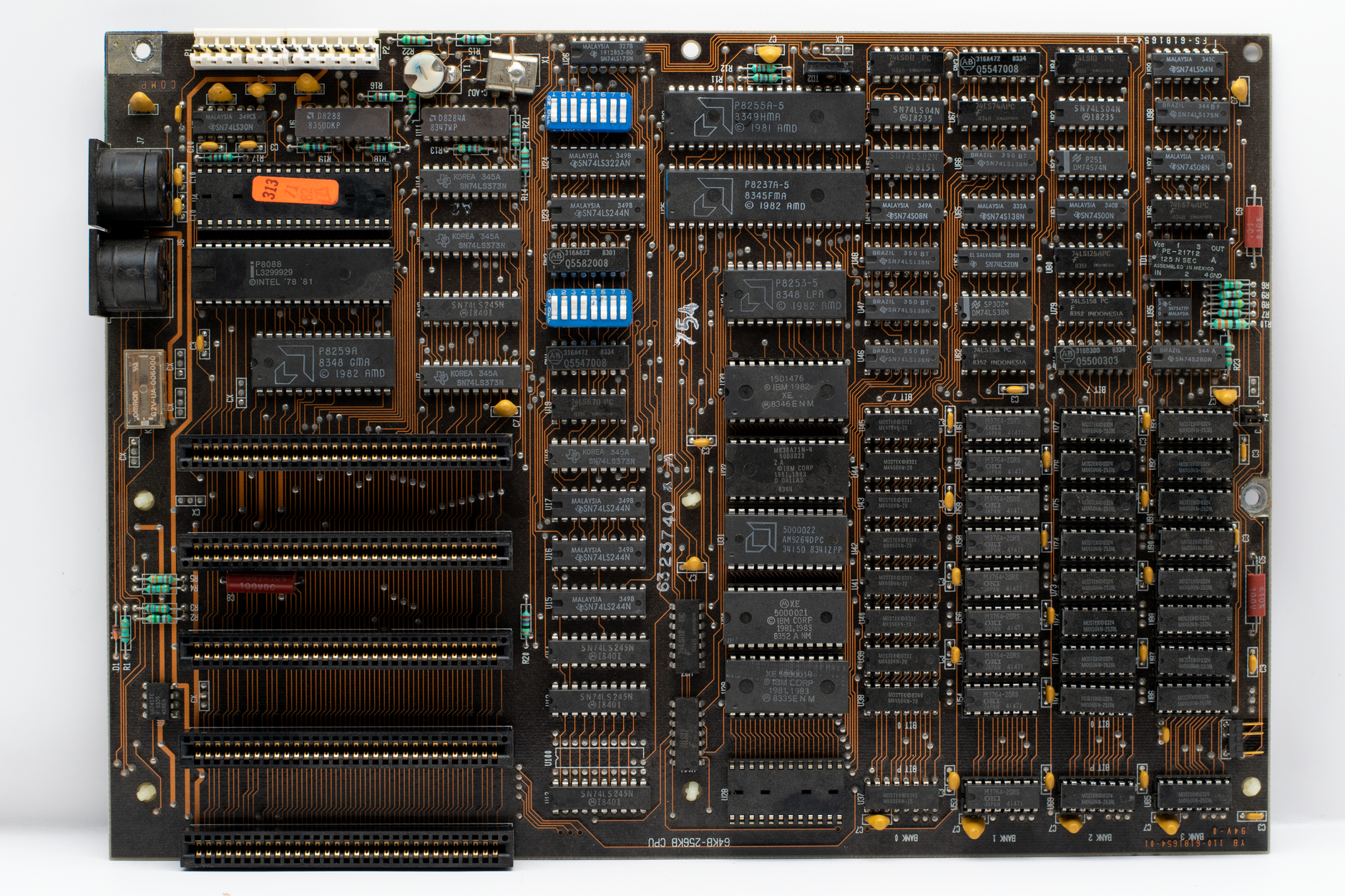
Logic gates are fundamental building blocks of digital circuits. They perform basic logical functions that underpin modern computing and electronic devices. Understanding logic gates is essential for anyone interested in electronics, computer engineering, or software development.
In this article, we will explore what a logic gate is, the different types of logic gates, how they function, and the truth tables associated with them. By the end of this piece, you will have a solid grasp of logic gates and their significance in digital circuits.
What Is a Logic Gate?
A logic gate is an electronic component that operates on one or more binary inputs to produce a single binary output. They use algebraic operations to manipulate these inputs according to defined logical rules. Logic gates form the backbone of digital systems, allowing them to perform calculations, make decisions, and process information.
The Basics of Logic Gates
Logic gates can be classified based on their function and the number of inputs they accept. The basic operations performed by logic gates include AND, OR, NOT, NAND, NOR, XOR, and XNOR. These gates can be combined to create complex circuits capable of completing a variety of tasks.
Binary Inputs and Outputs
Logic gates operate using binary values, typically represented as 0 and 1. The input of a logic gate refers to the binary values fed into it, while the output is the result of the logical operation based on those inputs. This binary state enables effective decision-making and calculations in digital systems.
Types of Logic Gates
There are several types of logic gates, each with unique functions. Each type of gate produces a specific output based on the inputs it receives. Below are the primary types of logic gates commonly used in digital circuits:
- AND Gate: Outputs 1 only if all inputs are 1.
- OR Gate: Outputs 1 if at least one input is 1.
- NOT Gate (Inverter): Outputs the opposite of the input (1 becomes 0 and vice versa).
- NAND Gate: Outputs 0 only if all inputs are 1 (the opposite of AND).
- NOR Gate: Outputs 1 only if all inputs are 0 (the opposite of OR).
- XOR Gate (Exclusive OR): Outputs 1 if the number of 1s in the inputs is odd.
- XNOR Gate (Exclusive NOR): Outputs 1 if the number of 1s in the inputs is even (the opposite of XOR).
Understanding Truth Tables
A truth table is a mathematical table that describes the output of a logic gate based on all possible combinations of its inputs. Truth tables are critical for understanding how each gate functions, and they serve as a perfect reference for evaluating logical operations.
Truth Table for the AND Gate
| A | B | Output |
|---|---|--------|
| 0 | 0 |   0    |
| 0 | 1 |   0    |
| 1 | 0 |   0    |
| 1 | 1 |   1    |
Truth Table for the OR Gate
| A | B | Output |
|---|---|--------|
| 0 | 0 |   0    |
| 0 | 1 |   1    |
| 1 | 0 |   1    |
| 1 | 1 |   1    |
Truth Table for the NOT Gate
| A | Output |
|---|--------|
| 0 |   1    |
| 1 |   0    |
Truth Table for the NAND Gate
| A | B | Output |
|---|---|--------|
| 0 | 0 |   1    |
| 0 | 1 |   1    |
| 1 | 0 |   1    |
| 1 | 1 |   0    |
Truth Table for the NOR Gate
| A | B | Output |
|---|---|--------|
| 0 | 0 |   1    |
| 0 | 1 |   0    |
| 1 | 0 |   0    |
| 1 | 1 |   0    |
Truth Table for the XOR Gate
| A | B | Output |
|---|---|--------|
| 0 | 0 |   0    |
| 0 | 1 |   1    |
| 1 | 0 |   1    |
| 1 | 1 |   0    |
Truth Table for the XNOR Gate
| A | B | Output |
|---|---|--------|
| 0 | 0 |   1    |
| 0 | 1 |   0    |
| 1 | 0 |   0    |
| 1 | 1 |   1    |
Applications of Logic Gates
Logic gates are critical components in various technology domains, especially in digital circuits and computing. Below are some of the common applications of logic gates:
- Circuit Design: Logic gates are used to design various types of digital circuits, including adders, multiplexers, and flip-flops.
- Microprocessors: Logic gates are the functional building blocks of microprocessors and microcontrollers.
- Memory Devices: Logic gates are involved in the design and operation of memory devices like RAM and ROM.
- Electronic Devices: Everyday electronics, such as smartphones and computers, rely heavily on logic gates for computation and control.
- Signal Processing: Logic gates can be used to filter and manage signals in various electronic applications.
Creating Complex Logic Circuits
By combining logic gates, engineers and designers can create complex logic circuits capable of handling intricate operations. Common configurations include combinational circuits and sequential circuits:
Combinational Circuits
Combinational circuits are composed of multiple logic gates that work together to produce a specific output based on the current input. They include circuits like adders (used in arithmetic operations) and multiplexers (which select data sources based on control signals).
Sequential Circuits
Sequential circuits use logic gates along with memory elements to produce outputs based on the current input as well as past input history. Flip-flops are a common example, used in memory storage and timing applications.
Building a Simple Logic Circuit
To better understand how logic gates function in a practical scenario, let’s build a simple logic circuit that uses an AND and an OR gate.
Components Required
- 1 x AND Gate
- 1 x OR Gate
- 2 x Input Switches
- 1 x Output LED
- Power Supply
Circuit Configuration Steps
- Connect the two input switches to the input terminals of the AND gate.
- Connect the output terminal of the AND gate to one of the input terminals of the OR gate.
- Connect the second input of the OR gate to one of the input switches.
- Connect the output terminal of the OR gate to the LED.
- Connect all components to the power supply according to their voltage requirements.
With this configuration, the output LED lights up based on the logical operations defined by the AND and OR gates. If both switches are on, the AND gate outputs a 1, and the LED is illuminated. If either switch is on, the OR gate will output 1, also lighting the LED.
Challenges and Limitations of Logic Gates
While logic gates offer numerous advantages, they also face certain challenges and limitations:
- Power Consumption: Logic gates consume power during operation, which can be a concern in battery-operated devices.
- Speed: The speed of logic operations can impact the overall performance of a digital circuit, particularly in high-frequency designs.
- Noise Margin: Digital circuits are prone to noise, which can cause errors in logic operations.
- Temperature Sensitivity: High temperatures can affect the behavior of logic gates, leading to potential malfunctions in sensitive applications.
The Future of Logic Gates in Technology
As technology advances, the design and implementation of logic gates continue to evolve. Innovations such as quantum computing and neuromorphic computing highlight new ways logic operations can be processed, aiming for greater efficiency and speed.
While traditional silicon-based logic gates are critical to modern electronics, future trends may lead to the adoption of newer technologies that improve speed and reduce power consumption, ultimately redefining computation.
Conclusion
Logic gates are indispensable components of digital circuits that perform essential operations in computing and electronics. Understanding how these gates work and their applications allows for innovation in various tech fields. Whether you’re designing simple circuits or diving into complex algorithms, a clear grasp of logic gates and their functions is crucial for success.
If you’re interested in exploring more technology fundamentals, consider checking out our articles on what a computer is and what an operating system is.